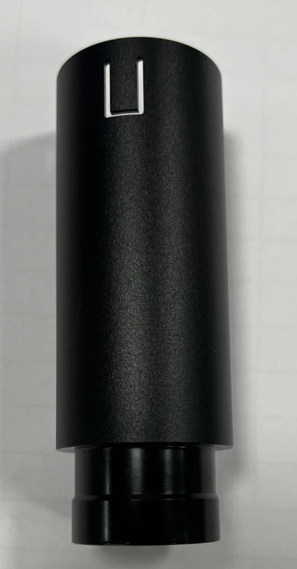
Blasting can deform the thin-wall cylinder, while its surface texture must match the customer sample. Dimensions are accepted in the finished surface-treatment condition, and the U-shaped slots must be burr-free.
Industry
Optics
Material
Per project drawing
Finish
Per project specification
Quantity
Confirmed per project
Drawings retain their original annotations.
01PRODUCT PHOTOGRAPHS
Product photographs
Product photograph 01Click to enlarge ↗Product photograph 02Click to enlarge ↗02TECHNICAL REQUIREMENTS
Machining challenges
Technical drawingClick to enlarge ↗01
Blasting can distort the thin-wall cylinder, so accuracy and appearance pull against each other
The cylinder wall is thin. In a conventional sequence, blasting after finish machining means the impact of #120 steel shot compresses and distorts the cylinder, pushing the critical cylindrical fit diameters and the φ0.02 mm cylindricity (relative to datum A) out of tolerance. The coarse texture the customer specifies cannot be achieved without abrasive impact, and the thin wall has little stiffness to resist it, so blasting forces cause expansion, contraction and loss of roundness, leaving parts that look right but fail on dimensions.
02
The blasted texture must match the customer sample, within a narrow process window
Specified areas are glass-bead blasted, and the texture and coarseness must match the customer's reference sample exactly. Small changes in media grade, air pressure, stand-off distance or traverse speed alter the surface micro-texture, and a finish that is too coarse or too fine will be rejected. Anodic film thickness is held at 10–16 μm, because variation in the film also changes the final visual appearance.
03
Multiple precision features, all dimensioned after surface treatment
The drawing states that all dimensions apply after surface treatment. They include a precision bore of φ30⁺⁰・⁰⁵⁵₊₀・₀₃, 0.02 mm cylindricity and U-slots; the U-slots must be burr-free and meet a pull-force assembly requirement. The usual route of finish machining before surface treatment does not work for this part, because blasting distortion and anodic film build-up together easily push fits and geometric tolerances out of their bands.
04
Precision U-slots with strict burr-free requirements
Two 120° U-slots must have no residual burrs or rolled edges. Cutting at the thin-wall sections easily raises burrs, and deburring must not scratch the blasted outer surface, which makes protecting the cosmetic surface difficult.
03PROCESS AND INSPECTION
Process solutions
01
A re-sequenced route: semi-finish machining → blasting → final finish machining
The usual order was changed. Semi-finish machining leaves a precise allowance, then blasting creates the coarse texture the customer requires. Once blasting has released its distortion, final finish machining removes the resulting error, so the φ0.02 cylindricity, critical bores and all other dimensions meet the post-treatment drawing tolerances while the required blasted appearance is kept.
02
Fixed blasting parameters matched to the sample
Blasting media, pressure, stand-off distance and exposure time are fixed, and the texture is compared with the customer sample for approval so the target coarse finish can be reproduced consistently. Non-blasted features are protected to avoid damaging precision surfaces still to be machined.
03
Closed-loop control of black anodising thickness
Black anodising thickness is held at 10–16 μm with uniform film growth, compensating for the dimensional build-up so finished dimensions stay within tolerance after anodising.
04
Precision deburring of thin-wall U-slots
Cutting parameters for the U-slots were optimised to reduce burr formation, and non-contact or compliant deburring leaves the slots free of burrs and rolled edges while protecting the blasted outer surface from scratches.
05
Final-state inspection across the whole process
Inspection is carried out after blasting, after finish machining and after anodising. Acceptance is based on the post-treatment state as the drawing requires, checking bore sizes, cylindricity, blasted texture, film thickness and the U-slots, so both appearance and precision dimensions are met.
Technical parameters and processes follow the project documentation. The drawing governs technical requirements; acceptance results follow project inspection records.
Product photograph 01Click to enlarge ↗Product photograph 02Click to enlarge ↗
02TECHNICAL REQUIREMENTS
Machining challenges
Technical drawingClick to enlarge ↗
01
Blasting can distort the thin-wall cylinder, so accuracy and appearance pull against each other
The cylinder wall is thin. In a conventional sequence, blasting after finish machining means the impact of #120 steel shot compresses and distorts the cylinder, pushing the critical cylindrical fit diameters and the φ0.02 mm cylindricity (relative to datum A) out of tolerance. The coarse texture the customer specifies cannot be achieved without abrasive impact, and the thin wall has little stiffness to resist it, so blasting forces cause expansion, contraction and loss of roundness, leaving parts that look right but fail on dimensions.
02
The blasted texture must match the customer sample, within a narrow process window
Specified areas are glass-bead blasted, and the texture and coarseness must match the customer's reference sample exactly. Small changes in media grade, air pressure, stand-off distance or traverse speed alter the surface micro-texture, and a finish that is too coarse or too fine will be rejected. Anodic film thickness is held at 10–16 μm, because variation in the film also changes the final visual appearance.
03
Multiple precision features, all dimensioned after surface treatment
The drawing states that all dimensions apply after surface treatment. They include a precision bore of φ30⁺⁰・⁰⁵⁵₊₀・₀₃, 0.02 mm cylindricity and U-slots; the U-slots must be burr-free and meet a pull-force assembly requirement. The usual route of finish machining before surface treatment does not work for this part, because blasting distortion and anodic film build-up together easily push fits and geometric tolerances out of their bands.
04
Precision U-slots with strict burr-free requirements
Two 120° U-slots must have no residual burrs or rolled edges. Cutting at the thin-wall sections easily raises burrs, and deburring must not scratch the blasted outer surface, which makes protecting the cosmetic surface difficult.
03PROCESS AND INSPECTION
Process solutions
01
A re-sequenced route: semi-finish machining → blasting → final finish machining
The usual order was changed. Semi-finish machining leaves a precise allowance, then blasting creates the coarse texture the customer requires. Once blasting has released its distortion, final finish machining removes the resulting error, so the φ0.02 cylindricity, critical bores and all other dimensions meet the post-treatment drawing tolerances while the required blasted appearance is kept.
02
Fixed blasting parameters matched to the sample
Blasting media, pressure, stand-off distance and exposure time are fixed, and the texture is compared with the customer sample for approval so the target coarse finish can be reproduced consistently. Non-blasted features are protected to avoid damaging precision surfaces still to be machined.
03
Closed-loop control of black anodising thickness
Black anodising thickness is held at 10–16 μm with uniform film growth, compensating for the dimensional build-up so finished dimensions stay within tolerance after anodising.
04
Precision deburring of thin-wall U-slots
Cutting parameters for the U-slots were optimised to reduce burr formation, and non-contact or compliant deburring leaves the slots free of burrs and rolled edges while protecting the blasted outer surface from scratches.
05
Final-state inspection across the whole process
Inspection is carried out after blasting, after finish machining and after anodising. Acceptance is based on the post-treatment state as the drawing requires, checking bore sizes, cylindricity, blasted texture, film thickness and the U-slots, so both appearance and precision dimensions are met.
Technical parameters and processes follow the project documentation. The drawing governs technical requirements; acceptance results follow project inspection records.