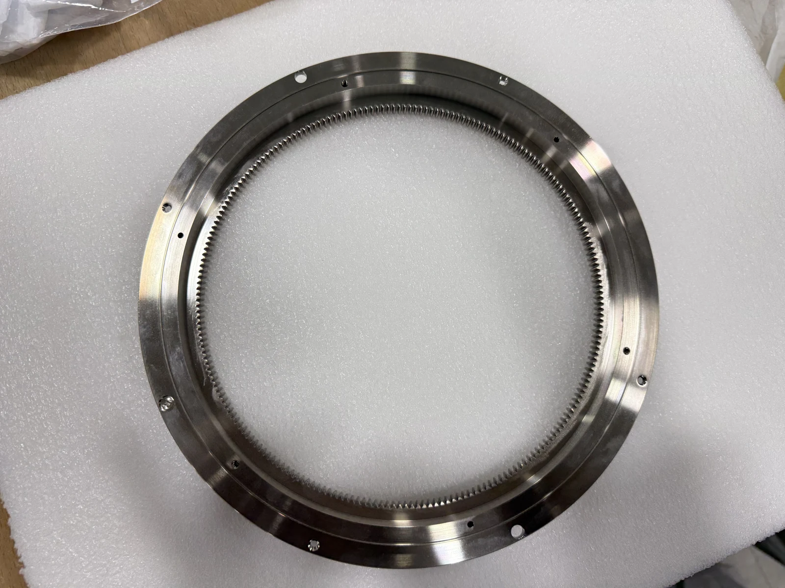
From the turned datum to gear shaping and surface finishing, setup alignment and thin-wall distortion are managed around the specified coaxiality requirement.
Industry
Medical Devices
Material
Per project drawing
Finish
Per project specification
Quantity
Confirmed per project
Drawings retain their original annotations.
01PRODUCT PHOTOGRAPHS
Product photographs
Product photographClick to enlarge ↗02TECHNICAL REQUIREMENTS
Machining challenges
Technical drawingClick to enlarge ↗01
φ0.03 mm coaxiality across operations, with high setup-error risk
The Φ228.6 datum diameter is turned on a CNC lathe, while the internal tooth profile is cut on a gear shaper in a second setup. Two setups on different machines accumulate locating error, which can easily push the coaxiality of the gear teeth relative to the turned datum beyond φ0.03 mm. The large-diameter thin-wall ring is not very rigid, and clamping forces cause slight distortion that magnifies the coaxiality error. The drawing specifies a demanding check: PG gauge pins are placed across the teeth and an outside micrometer takes 18 readings, with concentricity assessed from the maximum minus the minimum, so even small deviations are detected.
02
Controlling machining stress and distortion in a thin-wall ring
In a large-diameter thin-wall ring, the blank, turning and gear shaping all release internal stress, and the part easily goes oval or out of round. Even after machining passes inspection, the electroless nickel plating that follows can still cause distortion as stress is released. Stress-relief annealing of the blank and controlled allowances at each operation are needed to reduce machining stress.
03
Precision internal gear cutting with controlled tooth alignment and roundness
The internal ring gear has a high accuracy grade and a pitch circle diameter of Φ198. Shaping internal teeth in a large bore needs long tool overhang, which causes tool deflection that affects tooth form and ring roundness, so shaping fixtures, tool selection and cutting parameters are all tightly constrained.
04
Uniform electroless nickel thickness
The finished part is electroless nickel plated to 6 ± 2 μm. On a large-diameter thin-wall ring, uneven plating between the inner and outer diameters and at the edges can cause local over-thickness, and the coating must not upset the geometric accuracy already achieved, so build-up must not affect coaxiality or size. The part must be burr-free, with all sharp edges broken.
03PROCESS AND INSPECTION
Process solutions
01
High-precision alignment before gear shaping
After loading on the gear shaper, the Φ228.6 datum diameter turned on the CNC lathe is indicated and aligned, with runout held within 0.01 mm before cutting starts. This removes the locating error from the two setups at source and reliably achieves the φ0.03 mm coaxiality of the teeth relative to the datum required by the drawing.
02
Stress-relief annealing of the blank
The blank is stress-relief annealed first to release residual stress, reducing the risk of distortion and ovality after turning, gear shaping and nickel plating.
03
Staged, layered cutting
Rough and finish turning are separated with well-distributed allowances, and gear-shaping parameters are optimised to reduce tool deflection and protect tooth form and pitch circle accuracy.
04
Inspection exactly as the drawing specifies
Following the drawing's inspection method, ring-gear concentricity is measured with PG gauge pins and a micrometer at 18 points, reproducing the customer's acceptance conditions.
05
Electroless nickel process control
Electroless nickel thickness is controlled at 6 ± 2 μm with a uniform coating, and geometric tolerances are re-inspected after plating. Sharp edges are deburred and broken to meet the drawing's technical requirements.
Technical parameters and processes follow the project documentation. The drawing governs technical requirements; acceptance results follow project inspection records.
φ0.03 mm coaxiality across operations, with high setup-error risk
The Φ228.6 datum diameter is turned on a CNC lathe, while the internal tooth profile is cut on a gear shaper in a second setup. Two setups on different machines accumulate locating error, which can easily push the coaxiality of the gear teeth relative to the turned datum beyond φ0.03 mm. The large-diameter thin-wall ring is not very rigid, and clamping forces cause slight distortion that magnifies the coaxiality error. The drawing specifies a demanding check: PG gauge pins are placed across the teeth and an outside micrometer takes 18 readings, with concentricity assessed from the maximum minus the minimum, so even small deviations are detected.
02
Controlling machining stress and distortion in a thin-wall ring
In a large-diameter thin-wall ring, the blank, turning and gear shaping all release internal stress, and the part easily goes oval or out of round. Even after machining passes inspection, the electroless nickel plating that follows can still cause distortion as stress is released. Stress-relief annealing of the blank and controlled allowances at each operation are needed to reduce machining stress.
03
Precision internal gear cutting with controlled tooth alignment and roundness
The internal ring gear has a high accuracy grade and a pitch circle diameter of Φ198. Shaping internal teeth in a large bore needs long tool overhang, which causes tool deflection that affects tooth form and ring roundness, so shaping fixtures, tool selection and cutting parameters are all tightly constrained.
04
Uniform electroless nickel thickness
The finished part is electroless nickel plated to 6 ± 2 μm. On a large-diameter thin-wall ring, uneven plating between the inner and outer diameters and at the edges can cause local over-thickness, and the coating must not upset the geometric accuracy already achieved, so build-up must not affect coaxiality or size. The part must be burr-free, with all sharp edges broken.
03PROCESS AND INSPECTION
Process solutions
01
High-precision alignment before gear shaping
After loading on the gear shaper, the Φ228.6 datum diameter turned on the CNC lathe is indicated and aligned, with runout held within 0.01 mm before cutting starts. This removes the locating error from the two setups at source and reliably achieves the φ0.03 mm coaxiality of the teeth relative to the datum required by the drawing.
02
Stress-relief annealing of the blank
The blank is stress-relief annealed first to release residual stress, reducing the risk of distortion and ovality after turning, gear shaping and nickel plating.
03
Staged, layered cutting
Rough and finish turning are separated with well-distributed allowances, and gear-shaping parameters are optimised to reduce tool deflection and protect tooth form and pitch circle accuracy.
04
Inspection exactly as the drawing specifies
Following the drawing's inspection method, ring-gear concentricity is measured with PG gauge pins and a micrometer at 18 points, reproducing the customer's acceptance conditions.
05
Electroless nickel process control
Electroless nickel thickness is controlled at 6 ± 2 μm with a uniform coating, and geometric tolerances are re-inspected after plating. Sharp edges are deburred and broken to meet the drawing's technical requirements.
Technical parameters and processes follow the project documentation. The drawing governs technical requirements; acceptance results follow project inspection records.